Overview
In this post we’re going to dive into how to wire up a Victron Energy based camper van electrical system that uses their Smart lithium batteries which require an external BMS and provide two free wiring diagrams. The Smart lithium batteries are available in a variety of sizes/capacities but we prefer the 200 amp hour and 330 amp hour versions.
You might also want to check out this video tour of a system based off this design.
FREE Camper Van Power System Resources & Wiring Diagrams
If you're confused about your DIY camper van electrical or solar system, you've come to the right place. We have tons of resources including blog posts, videos and detailed example wiring diagrams (see below),If you're really stuck, we also offer consulting and design services. Our "choosing a system" page offers some additional advice and includes an example load calculation that you can use.Below are some of our example power systems for camper vans/RVs. The Victron-based systems all have a corresponding blog post, free detailed PDF example wiring diagram, and a corresponding best price product bundle. Ultimately, you'll probably customize your system to your particular needs and perhaps combine ideas from one or more of the example systems.
- A baseline camper van electrical system that uses lithium batteries with internal battery management systems (BMS) such as a Victron SuperPack, Battleborn, SOK, etc. This is our most affordable and simple system as well as the most DIY friendly.
- A more advanced camper van electrical system that uses Victron Smart lithium batteries with an external BMS and a Cerbo GX for monitoring. This system is a bit more complex and more costly, but adds features and allows for more battery storage in the same physical footprint. If you use the Victron Lynx Smart BMS you can upgrade to a dedicated secondary alternator with a Wakespeed regulator in the future.
- A super powerful (fast-charging) system that uses a dedicated secondary alternator. This system is the most expensive but also the most off-grid capable. We also have a 48-volt version of this system!
- We also have a power system accessories bundle that has all the circuit protection, shore power, distribution, and wiring you'll likely need.
Please consider purchasing your power system equipment from our store. Our bundles offer great pricing (yeah, better than Amazon), free shipping and you'll have access to expert support and you'll be supporting our ability to create more content!
Finally, there are a few things that we don't sell in our store (yet!) that you might need so we keep a list of these products in this Google Sheet of recommended camper van products.
First, what is a BMS?
In short, Battery Management Systems (BMS) listen to the batteries and are the device in charge of protecting them from being overly charged (over voltage), too discharged (under voltage), too hot or too cold.
Want to know more? Check out this deep dive video – but then remember to come back!
External BMS Trade Offs
In contrast to Victron’s SuperPack batteries or other popular battery brands like SOK that have built-in BMS systems, Victron’s Smart batteries use an external BMS. While this certainly adds complexity (which we discuss in this blog post).
Advantages
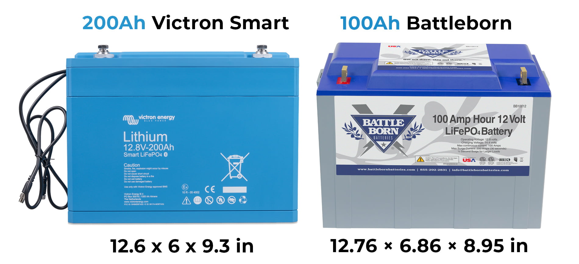
1) You can fit more power into a smaller space. The footprint of a Smart battery is about half that of an internal BMS SuperPack battery. So, you can fit 200 amp hours of storage into the same physical space as a 100 amp hour battery.
3) More finite control. Externalizing the BMS and using the types of devices that we discuss in this post enable much more control on how your power system will respond to the battery state. Here again, this adds complexity, but also adds features. For some folks this will be an advantage and for others, well, not so much.
4) If your BMS dies, you don’t have to replace the battery. As you probably know already, batteries are one of the most expensive parts of a power system. Externalizing the BMS allows you to replace that single part if it dies/breaks. If the BMS is built into the batteries you may have to replace the entire battery.
5) Higher voltage systems. Most of our customers prefer the simplicity of a 12 volt system. But, if you want to install a 48 volt (or higher) system, an external BMS can accommodate that in a way the built-in batteries may not.
VE.Bus BMS vs. Lynx Smart BMS
When using Victron Energy’s Smart Lithium batteries that require an external BMS, we typically use either the “simple” and affordable VE.Bus BMS or, in some cases, the more expensive but “fancier” (more feature-rich) Lynx Smart BMS. This post covers both and includes a free wiring diagram for both as well.
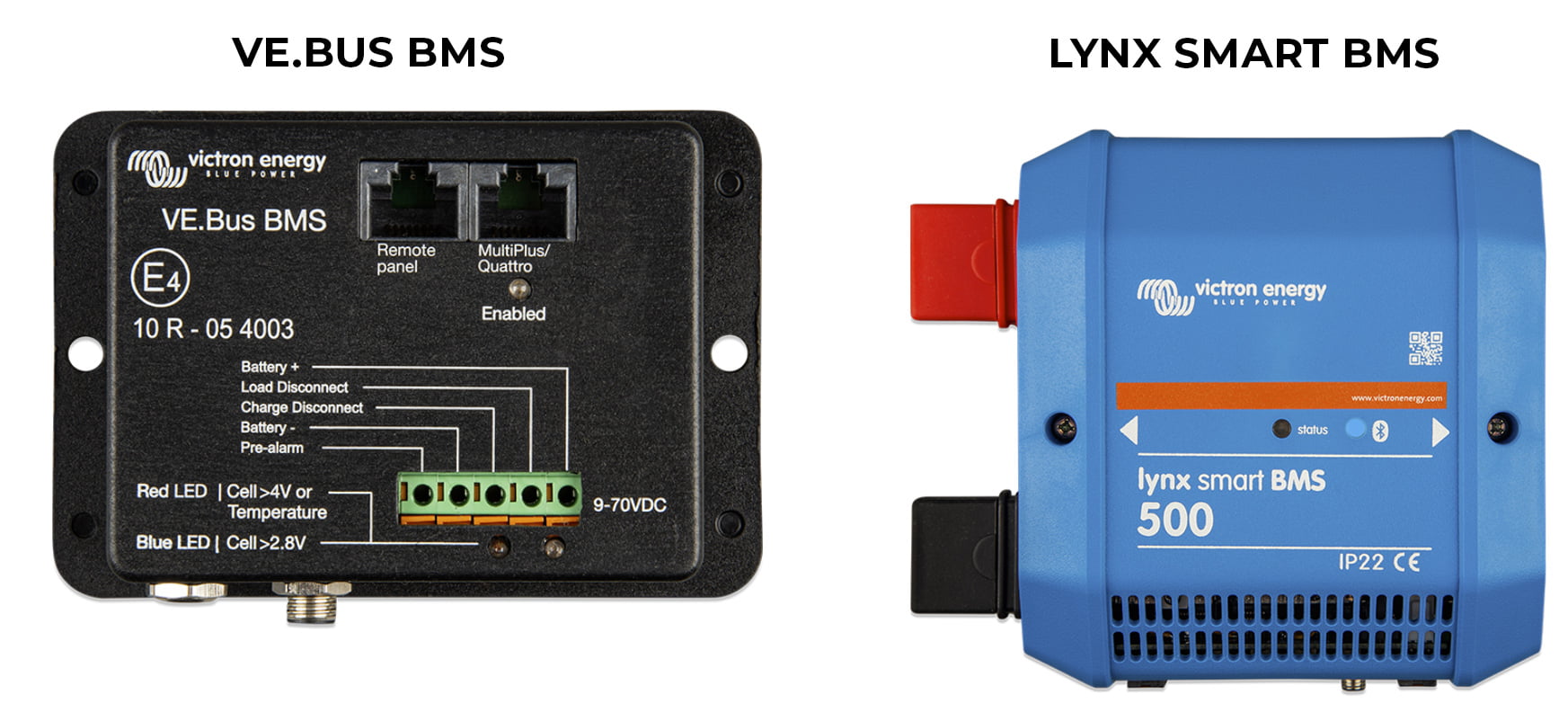
- It has an integrated shunt for battery monitoring so you don’t need a BMV-712 or SmartShunt in the system.
- It has a built-in 500 amp “contactor” that can disconnect charging/discharging when triggered by the batteries (temp/voltage) to anything that is wired up downstream (wired to the Lynx Distributor that is electrically connected to the “output” of this contactor”. I’ll explain how this is beneficial toward the end of the post.
- As suggested by its name, the Lynx Smart BMS is part of the Lynx “system”. If you take a look at the photo below you can see how the Lynx Smart BMS bolts onto the Lynx Distributor(s) to create a smart and tidy approach to your entire 12 volt DC bus. By using a Lynx Smart BMS with a Lynx Distributor you can “turn on” the features on the Lynx Distributor that you don’t get without it. There is a RJ10 (phone style) cable included with the Lynx Distributor that you can connect between it and the Lynx Smart BMS. When you do so, the Lynx Distributor will communicate if there is a blown fuse on any of its connections.
- Bluetooth connectivity. Anything made by Victron Energy with the word “Smart” in the name means that it has a Bluetooth connection that you can use with their VictronConnect app. You get a ton of info and configuration ability from the VictronConnect app with the Lynx Smart BMS including the ability to name each connection on the Lynx Distributor(s) (i.e.: “MultiPlus” or “Solar”) and notifications sent to the app and Cerbo GX if a fuse blows, etc.
- It has VE.Can connectivity to a Cerbo GX so that you can add CAN bus communication for things like DVCC (more on that below) or secondary alternator charging with something like a Wakespeed WS500 regulator.
Wiring Up The Batteries
Victron Energy’s Smart lithium batteries have two short, black wires attached to them with 3-conductor M8 connectors. You’ll begin by wiring them together (daisy chained) with these short wires and then use an extension cord (available in various lengths) to wire the string of batteries to the BMS you are using.
VE.Bus BMS – Controlling Charging/Discharging On Behalf of the Battery
The VE.Bus BMS can control a MultiPlus inverter/charger – which is both a charging and discharging device – through the VE.Bus. There is a VE.Bus connector on the BMS and also on the MultiPlus. This is an RJ45 (ethernet-style) connection.
The BMS also has so-called “allow to charge (ATC)” and “allow to discharge (ATD)” connections. These are basically relays that are “normally closed” allowing voltage to flow to the device they are connected to as a sort of “signal”. When the batteries “tell” the BMS they should not be charged or discharged the respective relay “opens” which stops the flow of electricity through the relay.
In a van power system, the allow to charge (ATC) is typically used for Orion DC-DC chargers and MPPT solar charge controllers.
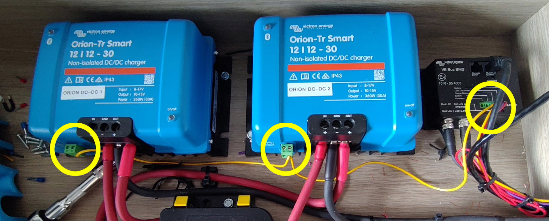
In the case of the Orion’s, they have something called “engine shutdown detection” which is a feature where they monitor the voltage of the vehicle battery (that they are wired to for charging). When it rises to a certain threshold (around 14 volts but can be adjusted in the settings), it assumes the vehicle is running and, therefore, the vehicle alternator is providing current to the vehicle battery which would mean that it’s safe to charge the “house” batteries without depleting the vehicle battery. When they sense this, the Orion’s turn themselves on and start charging your house batteries. This is awesome, easy and reliable “most of the time”, but suppose the BMS is “told” by the batteries that they shouldn’t be charged (perhaps it’s too cold)? In that scenario we’d want to override this automatic detection. Well, the Orion DC-DC chargers have remote terminals that can be wired up to a toggle switch in order to manually switch them on or off. The BMS can use this remote switch to turn off the unit when necessary – you simply wire up the ATC relay to the remote “H” (high) terminal. In normal circumstances this relay is “closed” (providing signal voltage) and when the BMS (on behalf of the batteries) decides the batteries should not be charged (too cold in our example), that relay “opens” which acts like the toggle switch being turned off thus disabling charging.
Below is a photo of two 30 amp Orion DC-DC chargers used in a system. They are wired in parallel for charging at 60 amps total as shown in the example wiring diagrams. The ATC wiring is circled in yellow.
Allow To Charge (ATC) With Victron SmartSolar MPPT Controllers
There are two ways for the BMS to control the charging output of a Victron Energy SmartSolar controller (such as this 100/50 model shown in our example wiring diagram). They typically come with a VE.Direct port. In systems where using a GX device such as the Cerbo GX paired up with a GX Touch 50 screen, you’ll want to use this VE.Direct port to connect the controller up to the Cerbo GX so that its data can flow into that system.
If you’re not using a GX device, you can instead use that VE.Direct port on the solar charge controller similar to the “remote” terminals on an Orion DC-DC charger with the so-called “Victron Energy VE.Direct Non-Inverting Remote On-Off Cable“. One side of that cable is wired to the allow to charge relay on the BMS and the other side has a VE.Direct style plug that can connect up to the solar charge controllers.
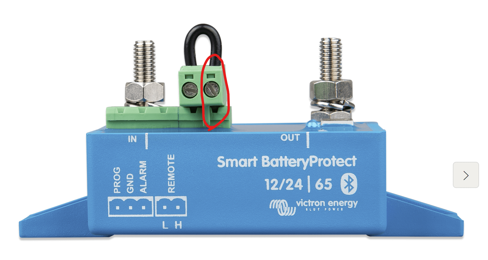
If you are using a GX device (like our example wiring diagram), you can use something called a Smart BatteryProtect. These are basically high current relays that can turn off the power flowing through them when triggered by something such a BMS (or wired to a switch, etc.). They come in various current ratings but we typically use the 100 amp version. These Smart BatteryProtects (SBPs) have the same kind of remote switch terminals that the Orion DC-DC chargers do which allows you to wire the allow to charge (ATC) relay on the BMS to a similar “H” connection on the SBP’s remote terminals to disable any charging sources connected to/through it. So, in our VE.Bus BMS sample wiring diagram, we show the charging outputs from the solar charge controllers wired up to a SBP and then to the positive bus (Lynx Distributor).
Other Loads – Allow to Discharge (ATD)
If your charging device doesn’t have anything that can respond to an ATC signal or some other “fancier” mechanism such as the other Victron communication protocols (VE.Bus, VE.Can, etc.), you can use something called a Smart BatteryProtect. These are basically high current relays that can turn off power flowing through them when triggered by a BMS. They come in various current ratings but we typically use the 100 amp version. These Smart BatteryProtects (SBPs) have the same kind of remote switch terminals. So, just like an Orion DC-DC charger, where you could wire up a toggle switch to control their on/off state (allowing current to flow or not), you can also use wire their “H” (high) remote terminal to a BMS ATC (allow to charge) relay.
Other Loads – Allow to Discharge (ATD)
As mentioned earlier, there are also times where the battery “tells” the BMS that it shouldn’t be discharged as well – typically when the battery is deeply discharged (low voltage) and would be damaged if the loads continue to discharge the battery (if you keep running your refrigerator/lights/fan). The Smart BatteryProtects (SBPs) are useful in this scenario as well. In our example system we show a SBP wired between the Lynx Distributor (DC positive and negative bus bar) and the 12 volt DC load center/fuse box. Then the BMS’ allow to discharge (ATC) relay signal wire is connected to the “H” (high) side of the SBP remote terminal. In this way, the BMS (again, on behalf of the batteries) can disconnect these loads when necessary.
Note, if you’re using a Cerbo GX in a system with a VE.Bus BMS, connect the power supply (12VDC positive) to the ower in V+ on the Cerbo GX to the “load disconnect” (ATD) terminal on the VE.Bus BMS. Then, for the VE.Bus connection, use the port “MultiPlus/Quattro” on the VE.Bus BMS – don’t use the “remote panel” port.
Using a Lynx Smart BMS
We’ve already discussed some of the advantages (extra features) of the Lynx Smart BMS. Now let’s dive into how using it in a power system differs from the VE.Bus BMS. Again, we’re providing an example wiring diagram of a system using both BMS options!
The first important thing is that a Lynx Smart BMS needs to be paired up with a “GX Device”. In almost all cases, that GX device would be Victron’s Cerbo GX (we’re working on another blog post about that!). The Lynx SmartBMS is connected via a VE.Can connection to the Cerbo GX which enables some new magic: DVCC…
DVCC – Distributed Voltage and Current Control
In short, DVCC allows the Lynx Smart BMS to control charging and discharging (as well as charging parameters) through the Cerbo GX on the DVCC capable devices. In a typical van power system those would be a MultiPlus inverter/charger, Victron MPPT solar charge controllers and, perhaps a Wakespeed regulator used with a secondary alternator.
In Victron’s words:
“Enabling DVCC changes a GX device from a passive monitor into an active controller. The available features and effects of enabling DVCC depend on the type of battery used. The effect also depends on the installed Victron components and their configuration.”
With DVCC enabled, the Lynx Smart BMS will automatically configure the “charging profile” for the batteries (adjusts the discharge current, charge current, charge voltage, etc.). Without DVCC, the installer must manually configure all the charging sources in their system. A typical van system will have at least a few charging sources: an inverter/charger, DC-DC chargers and solar charge controllers. Most Victron charging devices can be configured using VictronConnect via Bluetooth. However, MultiPlus inverter/chargers cannot be configured with Bluetooth – instead you must configure via the “VE.Bus” by using a MK3-USB adapter. To further complicate matters, when using a VE.Bus BMS, MultiPlus inverter/charges must be configured using VE.Configure including adding an “assistant” (detailed in this blog post).
More about DVCC:
https://www.victronenergy.com/media/pg/CCGX/en/dvcc—distributed-voltage-and-current-control.html
So, DVCC simplifies the configuration of DVCC compatible chargers (“smart things”). But we still need to consider the “dumb things” that don’t have communication ports (VE.Direct/VE.Can/VE.Bus, etc.). In a van power system, that is stuff like our 12 volt DC loads (fuse box/load center) that were run through the Smart BatteryProtect when using the VE.Bus BMS. The Orion DC-DC charges are also “dumb” in this sense.
Remember that one of the features of the Lynx Smart BMS was a 500 amp “contactor”? Here’s where that comes into play. Below (again) is the same illustration we showed earlier detailing how you might wire a system where your batteries are wired in parallel by connecting each to a Lynx Power In (far left). This allows up to 4x batteries to be connected to a combination DC positive and DC negative bus bars. In the middle of the illustration is the Lynx Smart BMS which is electrically connected to the Lynx Distributor on the left (battery connections) and passes their current onto the BMS. Inside the Lynx Smart BMS is the shunt that will monitor your electrical use and report on the state of your battery. Also inside there is that 500 amp “contactor”. Then, on the right side a second Lynx Distributor used for the loads and charging sources. This is also electrically connected to the Lynx Smart BMS and it’s where you’d wire up your inverter/charger, solar controller output, DC-DC charger output, etc.
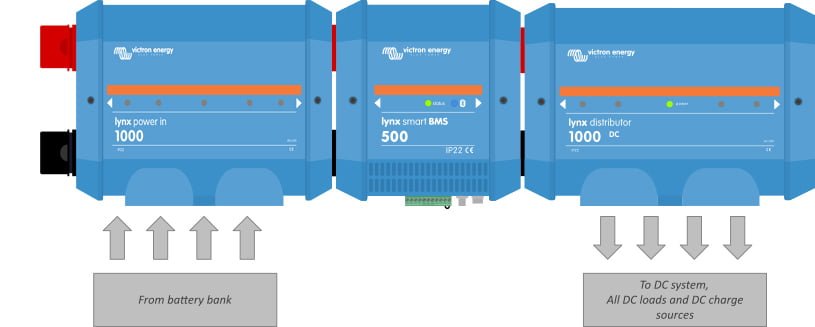
Does this mean you don’t need to use a Smart BatteryProtect for your 12 volt DC loads (wired to the ATD relay) or to wire up the Orion DC-DC chargers to the ATC relay through their remote terminals? Yes, technically it does if you want to keep things as simple as possible. However, the Lynx Smart BMS does have the same kind of ATC and ATD relays that the VE.Bus BMS does but the reason you might want to use them is somewhat nuanced…
The contactor in the BMS is triggered to open (cut off power) when the battery cell voltage (there are many cells in each battery that generate the nominal 12 volts) reaches 2.6 volts (a deeply discharged battery bank). Meanwhile the ATD relay would open at the slightly higher battery cell voltage of 2.8 volts. Thus, by wiring up your ATD to something like a Smart BatteryProtect, you can stagger the system shutdown so that you can turn off many of your “non-essential” loads (those connected via a Smart BatteryProtect) prior to the entire system being disabled. So, perhaps you cut off your loads like a fridge/fan/etc. but want to keep monitoring like the Cerbo GX running longer. Or, in marine applications, the use case is a bit more clear – it’s fine to disable the fridge or some lights in a situation where the batteries are dangerously low, but the navigation equipment should continue to operate while we figure out how to get some charge into these batteries!
Example Wiring Diagrams
One thing we always tell our customers is that there are MANY ways to wire up an electrical system that is safe and functional. Even when you use most of the same or similar components, you can approach the configuration slightly differently. There are a ton of considerations that lead to these small differences – everything from preference to space constraints to budget. In light of this, we are presenting two versions of the example wiring diagram using the Lynx Smart BMS below.
Version 1 is the most complex in the sense that it uses a pair of Smart Battery Protects (one on the load side and another on the charging side). Version two does not. As previously mentioned in this post, the primary advantage to adding Smart Battery Protects is to enable a “staggered” shut down of the system.
Version 2 has a simplified solar system with a single array of panels wired in series through a single charge controller while version 1 has two arrays/controllers.
Version 2 uses 2x 330 amp hour Victron Energy Smart batteries instead of 3x of the 200 amp hour batteries. Notably, the 330 amp hour version of these batteries is not that much bigger than the 200 am hour battery despite having vastly more capacity. We always recommend at least two of these Smart batteries in a system with a MultiPlus 12/3000/120.
Version 2 uses one Lynx Power In and one Lynx Distributor. The Power In is used to wire the batteries up in parallel and is located on the left side of the Lynx Smart BMS. Also, since there is a “contactor” (big switch) integrated into the Lynx Smart BMS we can eliminate the main battery switch shown in example wiring diagram 1. The second Lynx Distributor is electrically “downstream” from this contactor/switch and is used for all the loads and charging sources just like example diagram #1. Simplifying the wiring in this way also allows us to remove the main 400 ANL fuse shown in wiring diagram #1 in favor of terminal/MRBF fuses on each battery in example wiring diagram #2.


